Output - Encoder Emulation
Overview
 Encoder Emulation
Emulated encoder allows the AKD2G to output encoder like signals which follow the position from one of the different feedback inputs. The output can have a different resolution or be a different type compared to the input. For example, the source could be an SFD and the output could be an incremental encoder.
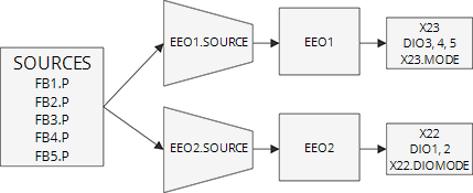
Each EEO (Emulated Encoder Output) unit is associated with a connector. You may need to set the mode of the connector to the X23.MODE or X22.DIOMODE to force the EEO signals to be output from the connector.
When using Q quad B mode, EEO#.MODE 0, the maximum speed that can be generated is

When using cw/ccw or step/dir modes, EEO#.MODEs 1 or 2, the maximum speed that can be generated is

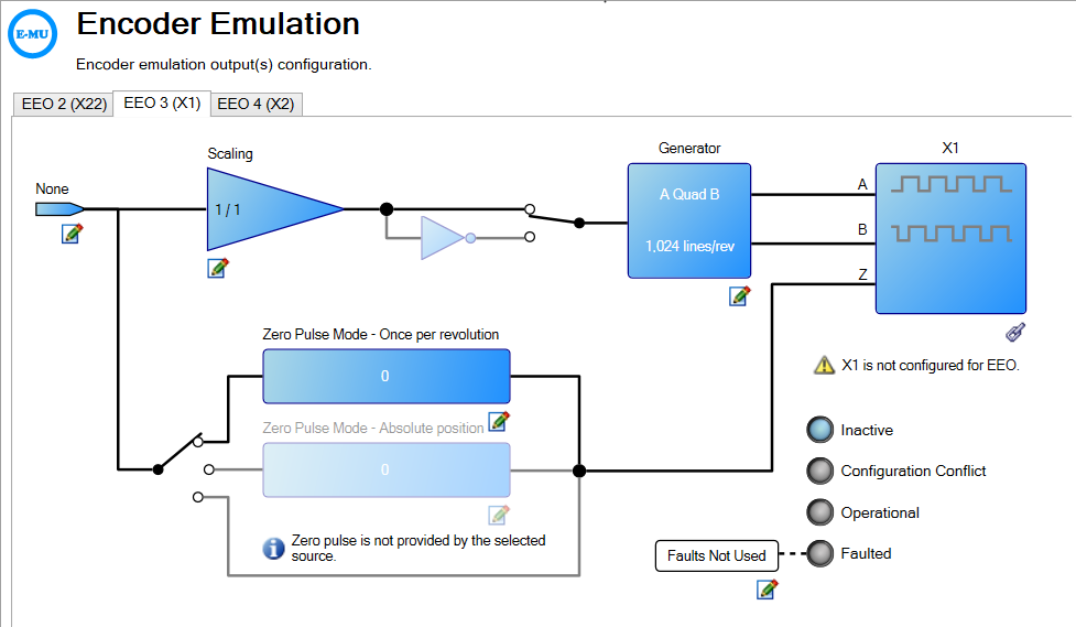
Encoder Emulation View
Configuration
| Element | Property | Description | Parameter | |||||||||||||
|---|---|---|---|---|---|---|---|---|---|---|---|---|---|---|---|---|
| Encoder Emulation Source |

|
Feedback source |
This parameter sets the position source used to drive the EEO generator. 1 – Feedback1 2 – Feedback 2 3 – Feedback 3 4 – Feedback 4 5 – Feedback 5 |
|||||||||||||
| Scaling |
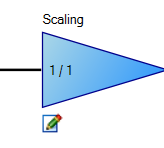
|
Ratio In | The Scaling node allows the user to edit the values of Position Gain Ratio Configuration keywords EE0#.PIN and EE0#.POUT. The Scaling node only appears in the diagram if the EEO#.PIN and EEO#.POUT keywords exist. | EEO#.PIN
|
||||||||||||
| Ratio Out | EEO#.POUT | |||||||||||||||
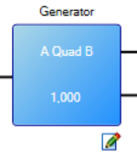
| EncoderEmulation Output Generator |
|
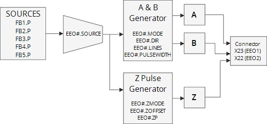
Mode |
This parameter specifies the type of output waveform an EEO generator will create. 0 – A Quad B 1 – CW/CCW 2 – Step/Direction |
EEO#.MODE | ||||||||||||
| Lines | Sets how many lines are output for one revolution of the source feedback. | EEO#.LINES | ||||||||||||||
| Pulse Width | Sets the pulse width from the CW/CCW and step/dir mode signals. | EEO#.PULSEWIDTH | ||||||||||||||
| Emulated Output Direction | Direction | Sets the direction of the ouput with respect to the source | EEO#.DIR | |||||||||||||
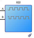
| X22 |
|
Connector |
Sets the connector function to either Feedback (FP), Emulated Encoder (EEO), or general purpose I/O (GPIO). X22 connector functionaliyt may also set within Hardware Configuration. Also see Feedback Connector X22 |
|||||||||||||
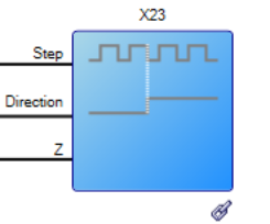
| X23 |
|
Sets the connector function to either Feedback (FP), Emulated Encoder (EEO), or general purpose I/O (GPIO). X23 connector functionality may also set within Hardware Configuration. See also Feedback Connector X23 |
X23.MODE | |||||||||||||
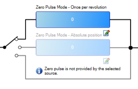
| ZeroPulse Mode | Mode | Sets the type of Z pulse (index pulse) an EEO generator will create. | EEO#.ZMODE | |||||||||||||
| Configure ZeroPulse |
|
ZeroPulse Mode - Once per revolution | This parameter sets the position within each revolution where the Z pulse will be generated, when the one Z pulse per revolution mode is selected (EEO#.ZMODE 0) | EEO#.ZOFFSET | ||||||||||||
| Zero Pulse Mode - Absolute position | This parameter sets the position of the Z pulse when the absolute Z pulse mode is selected (EEO#.ZMODE 1). | EEO#.ZP | ||||||||||||||
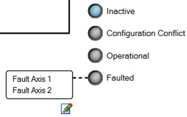
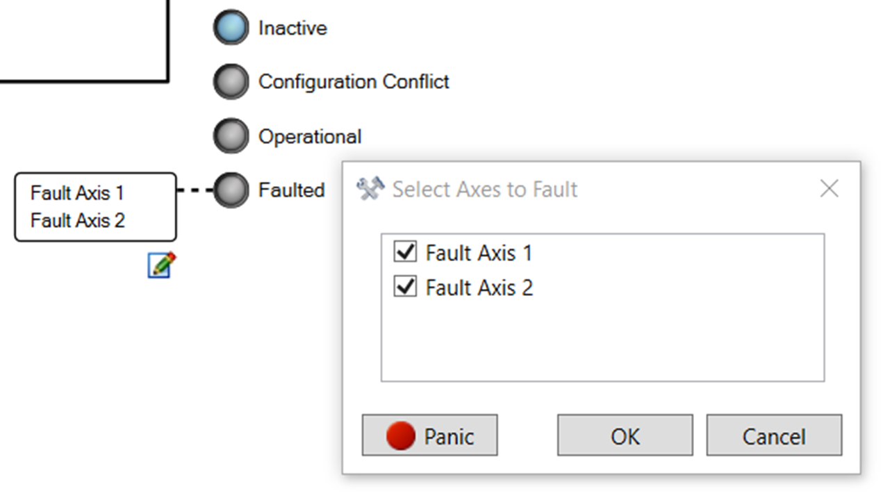
| EEO Status LEDs |
|
Four LEDs (Inactive, Configuration Conflict, Operational, and Faulted) which display the current status. The LEDs are only shown in the diagram if the EEO#.STATUS keyword exists and only one LED is illuminated at a time. | EEO#.STATUS | |||||||||||||
| Fault Axis Node |
|
The fault axis node lists axes to be faulted using the command EEO#.FAULTAXIS. Clicking the node allows the user to edit the EEO#FAULTAXIS keyword value by selecting the axis or axes to fault. This node only appears in the diagram if the EEO#.FAULTAXIS and EEO#.STATUS keywords exist. The EEO#.FAULTAXIS values can be viewed in the Watch List.
|
EEO#.FAULTAXIS |

Examples
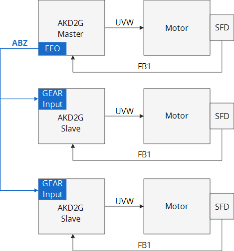
Master in a Master/Slave System
EEO can be used to synchronize several slave axes with a position from the master axis. Each slave axis would be able to coordinate its motion with functions like Electronic Gearing.
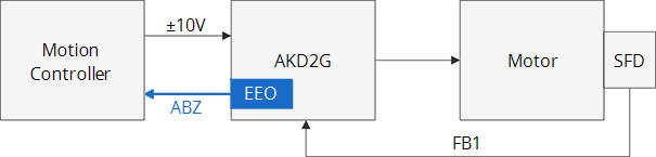
Position Feedback to an Analog Controller
EEO is commonly used when the AKD2G is replacing a simpler drive that was being controlled by a motion controller using a ±10V velocity or torque command. The motion controller is typically closing the position or velocity loop and need the ABZ encoder signals for the feedback to its loops. EEO allows the motor to use a modern feedback like SFD connected to the drive and then output the emulated encoder outputs that are passed to the motion controller.